
 English
 中文简体
中文简体 Español
 Português
 Deutsch
 русский
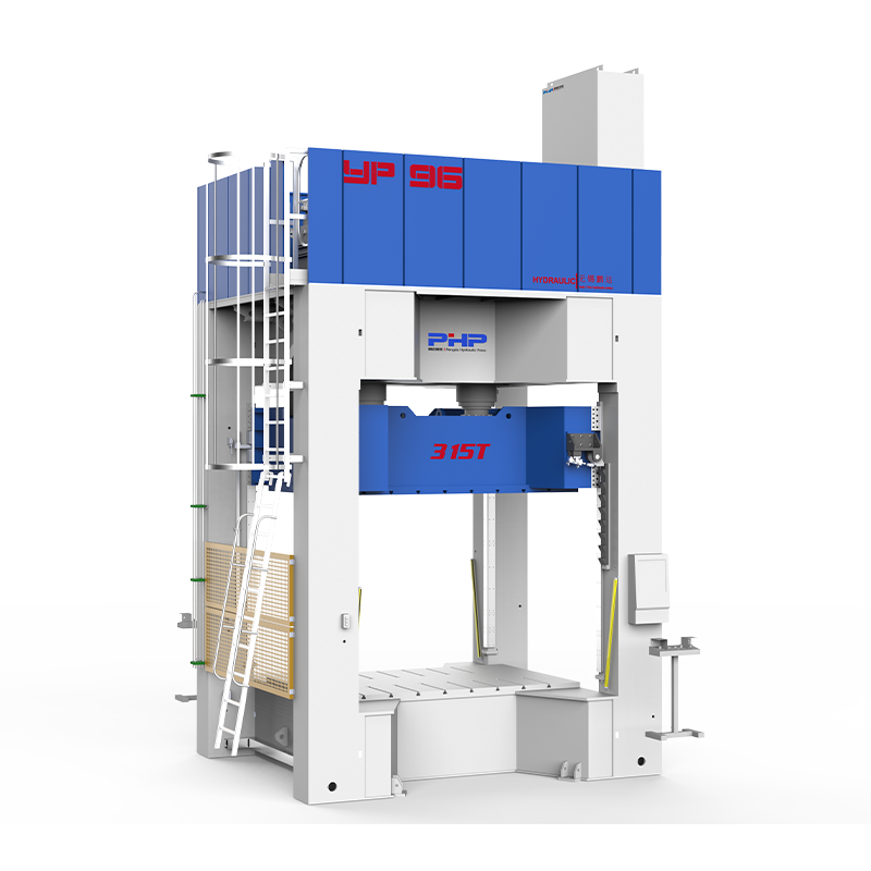
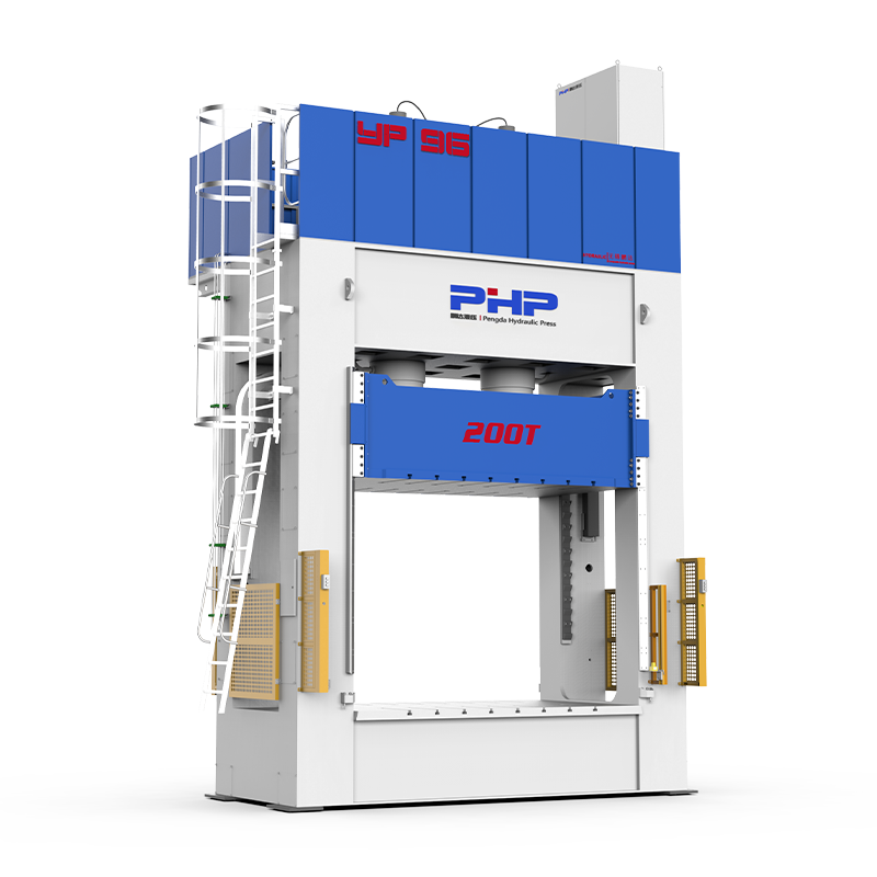


Producing an SMC part does not end when the compression molding press opens. Most molded components still require edge trimming, hole machining, flash removal, cutouts, or dimensional finishing before assembly.
The trimming method can directly affect dimensional accuracy, edge quality, cycle time, tool consumption, dust generation, and ultimately the cost per finished component.
For automotive panels, electrical enclosures, battery components, appliance parts, and other compression-molded products, manufacturers commonly choose among CNC routing, abrasive waterjet cutting, die trimming, sawing or grinding, manual trimming, and, in selected applications, laser cutting.
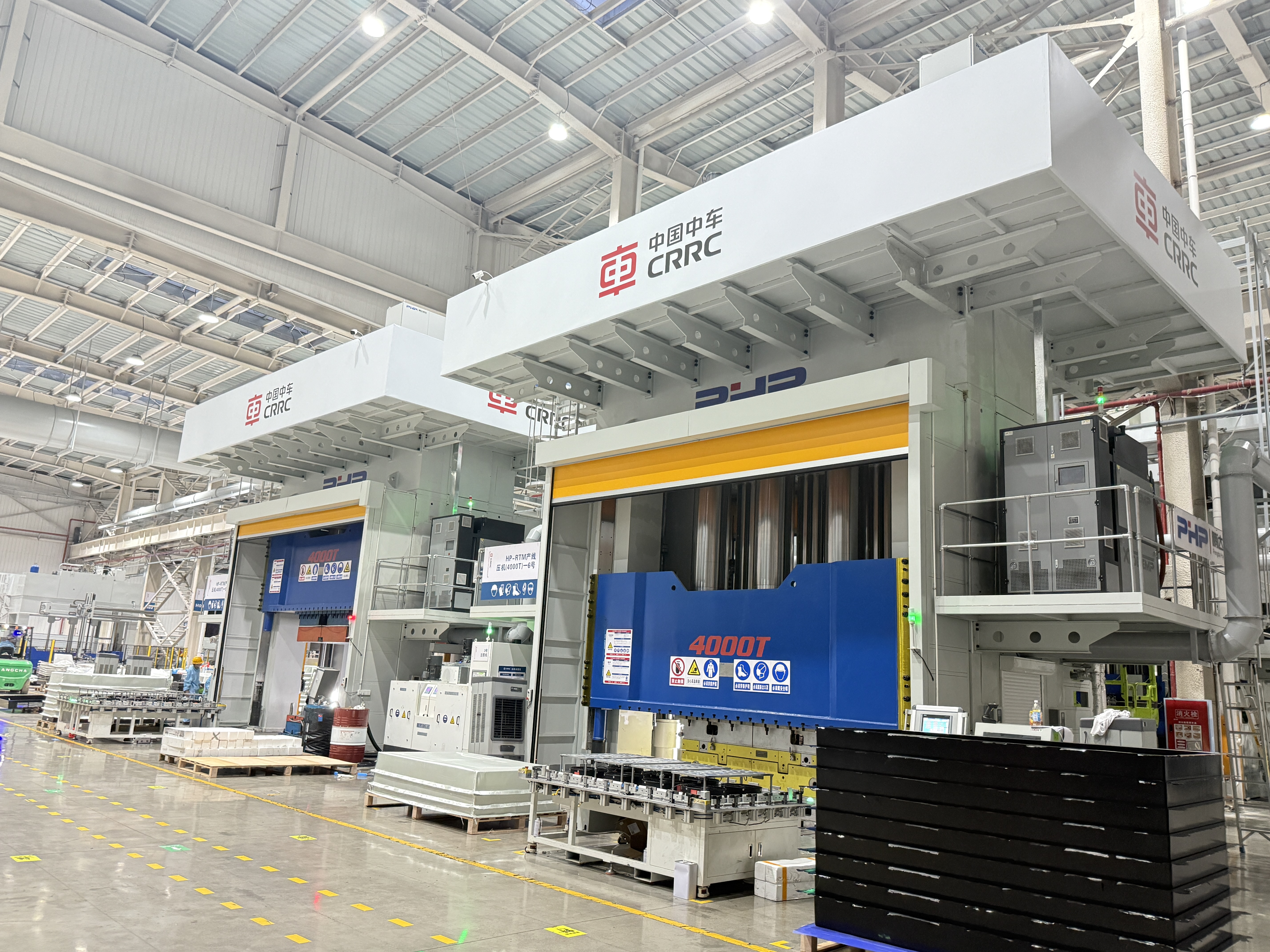
There is no single best method for every SMC component. The correct choice depends on part geometry, SMC formulation, wall thickness, production volume, tolerance requirements, downstream finishing, and the level of automation required.
Content
- 1 How to Choose an SMC Part Trimming Method
- 2 CNC Routing, Waterjet, Die Trimming and Other Methods
- 3 Example: Trimming a 200 × 300 × 3.5 mm SMC Part
- 4 Fixturing and Automated SMC Trimming Cells
- 5 Dust Control, Worker Safety and Waste Handling
- 6 Inspection and Post-Trim Finishing
- 7 Which SMC Trimming Method Is More Economical?
- 8 Planning an SMC Production Line
- 9 FAQ
- 9.1 How do I choose the best trimming method for an SMC part?
- 9.2 What CNC settings should be used for SMC routing?
- 9.3 Can SMC parts be laser cut?
- 9.4 How can movement be prevented during high-speed routing?
- 9.5 How should SMC trimming dust be controlled?
- 9.6 How do CNC routing and die trimming costs compare?
How to Choose an SMC Part Trimming Method
A practical trimming decision should begin with five questions:
- What is the annual production volume?
- How complex is the trim contour?
- What dimensional tolerance is required?
- How thick and abrasive is the SMC material?
- Will the trimming process be manual, CNC-based, or integrated into an automated production cell?
For prototypes and small production runs, flexible processes such as CNC routing and waterjet cutting usually avoid the cost of dedicated trim tooling. For stable, high-volume automotive production, die trimming can justify a much larger initial tooling investment because of its short cycle time.
CNC routing occupies the middle ground. It is programmable, suitable for holes and complex profiles, and can be incorporated into robotic or automatic production cells.
| Trimming Method | Typical Application | Production Volume | Flexibility | Accuracy Potential | Initial Tooling Cost |
|---|---|---|---|---|---|
| CNC routing | Complex contours, holes, slots | Low to high | High | High | Medium |
| Abrasive waterjet | Thick or difficult composite profiles | Low to medium | Very high | High | Medium |
| Die / press trimming | Repetitive production parts | High | Low | High after tooling validation | High |
| Saw / abrasive cutting | Straight or simple edges | Low to medium | Medium | Medium | Low |
| Manual trimming | Prototype, repair, secondary finishing | Low | Very high | Operator-dependent | Low |
| Laser cutting | Selected thin or special composite applications | Application-dependent | High | Potentially high | High |
Example 1: High-Volume Automotive Exterior Component
Consider an SMC automotive panel produced at 60,000 pieces per year with a stable design and a repeatable trim line.
A dedicated die-trimming operation or highly automated CNC trimming cell may provide better economics than repeatedly machining every edge on a general-purpose machine.
The larger tooling investment is distributed across tens of thousands of parts.
Example 2: Low-Volume Energy Equipment Enclosure
Now consider an SMC enclosure produced at only 2,000 pieces annually, with several product sizes and regular engineering changes.
A CNC router or waterjet system is normally easier to reprogram than a dedicated trimming die.
A hybrid process can also make sense. Waterjet cutting may remove large sections quickly, followed by CNC routing of mounting holes, critical interfaces, and high-tolerance features.
CNC Routing, Waterjet, Die Trimming and Other Methods
SMC contains reinforcement, resin, and often mineral fillers. These ingredients make the material very different from machining aluminum or unfilled thermoplastics.
Glass fibers, carbon fibers, and fillers can accelerate tool wear. Published machining studies on SMC have shown that cutting forces increase as tools wear, meaning tool condition should be treated as a process variable rather than simply waiting for visible tool failure.
CNC Routing
CNC routing is one of the most versatile solutions for SMC trimming.
It can process:
- external contours;
- holes and openings;
- slots;
- mounting features;
- edge finishing;
- multiple part variants using different CNC programs.
For initial process development, manufacturers may evaluate spindle speeds in approximately the 12,000–24,000 rpm range with suitable small-diameter composite-cutting tools. Feed rates may begin around 1–6 m/min and then be optimized through cutting trials.
These figures are process-development starting points, not universal settings.
Final parameters depend on fiber loading, filler content, thickness, cutter geometry, tool diameter, spindle rigidity, fixture stiffness, required edge finish, and extraction performance.
Carbide tooling can be used for many applications, while diamond-coated or PCD tools may be evaluated where abrasive wear becomes a major production cost.
A useful tool-change strategy is not simply:
Replace the cutter after X parts.
Instead, monitor:
- accumulated cutting length;
- spindle load;
- cutting force if available;
- edge roughness;
- burr or fiber breakout;
- dimensional drift.
The tool should be changed when measurable quality deterioration begins, rather than according to an arbitrary universal part count.
Abrasive Waterjet Cutting
Abrasive waterjet machining removes material without creating the same heat-affected zone associated with thermal cutting.
It is therefore attractive for composite components where minimizing thermal damage is important.
Typical process-development variables include:
- water pressure;
- abrasive flow rate;
- abrasive particle size;
- nozzle diameter;
- stand-off distance;
- traverse speed;
- piercing strategy.
Industrial systems may operate in roughly the 250–400 MPa pressure range, with garnet abrasives such as approximately 80 mesh frequently used as a starting point for process trials.
However, increasing traverse speed simply to shorten cycle time can increase kerf taper or reduce lower-edge quality.
Research involving abrasive waterjet trimming of chopped-fiber SMC has demonstrated that suitable operating conditions can produce relatively uniform surfaces with limited fiber pull-out.
Die or Press Trimming
Die trimming is particularly attractive when:
- production volume is high;
- part geometry is stable;
- trim lines repeat from part to part;
- short takt time is important.
The trimming tool must be designed around the actual molded component rather than nominal CAD geometry alone.
Mold shrinkage, springback, part warpage, thickness variation, and positioning repeatability all affect final trim accuracy.
Required press force should be calculated from the total cutting perimeter, material thickness, effective shear resistance, number of simultaneous trimming features, and an appropriate engineering safety factor.
For this reason, stating that every SMC component needs a specific fixed trimming tonnage would be misleading.
The main disadvantage of die trimming is tooling investment. If the component design changes frequently, modifying or replacing the trim die can eliminate much of the economic advantage.
Laser Cutting
Laser cutting offers fast non-contact motion and flexible CNC programming, but it should not automatically be considered the preferred solution for SMC.
Thermoset resin matrices and reinforcing fibers respond differently to concentrated thermal energy. Depending on the material formulation and laser conditions, potential issues include:
- matrix degradation;
- discoloration;
- carbonized edges;
- smoke generation;
- heat-affected zones;
- changes in bonding surfaces.
For this reason, laser parameters such as power, focal position, assist gas, scanning speed, and number of passes should be developed through coupon testing with the actual SMC formulation.
For many conventional glass-fiber SMC components, routing, waterjet, or mechanical trimming is easier to qualify.
Example: Trimming a 200 × 300 × 3.5 mm SMC Part
Consider a simplified enclosure component with the following requirements:
- Part size: 200 × 300 mm
- Thickness: 3.5 mm
- Approximate trim path: 1,000 mm
- Required tolerance: ±0.30 mm
- Annual volume: 40,000 parts
- Several drilled mounting holes
For CNC routing, machining time can be estimated as:
Cutting time = toolpath length ÷ effective feed rate
If an effective programmed feed rate of 3 m/min is validated:
1.0 m ÷ 3 m/min ≈ 20 seconds
This does not mean the complete part cycle is 20 seconds.
The production calculation must also include:
- robot or operator loading;
- part location;
- tool approach and retract;
- hole machining;
- unloading;
- dust removal;
- tool changes;
- inspection allowance.
If loading, positioning, drilling, routing, and unloading result in a 50-second total cycle, that number—not the theoretical cutting time—should be used for capacity planning.
For 40,000 stable parts per year, a manufacturer should then compare the annual machining cost against the amortized cost and shorter takt time of dedicated die trimming.
That is the correct way to compare processes economically.
Fixturing and Automated SMC Trimming Cells
Accurate cutting equipment cannot compensate for poor workholding.
SMC parts may contain curved surfaces, variable wall thicknesses, molded ribs, and residual distortion. Excessive clamping force can deform the part during machining and cause dimensional errors after it is released.
Common fixture options include:
Vacuum Fixtures
Vacuum fixtures provide distributed holding force and fast loading, particularly for large shell-shaped components.
They are effective when sufficient sealing area is available.
Mechanical Clamping
Mechanical clamps provide stronger positive retention but should be positioned outside critical cosmetic or measurement surfaces.
Applying excessive clamping pressure to unsupported SMC walls can temporarily distort the component.
Locating Pins and Dedicated Nests
A production fixture often combines a contour nest with locating pins and selected clamps.
A 3-2-1 datum strategy can be used where appropriate to establish a repeatable machine coordinate system while avoiding unnecessary over-constraint.
The fixture should provide clearance below the trim path so the cutter does not contact the fixture.
A robust automated sequence may look like this:
SMC Compression Press → Robotic Demolding → Cooling/Stabilization → Part Positioning → CNC or Robotic Trimming → Drilling → Dust Removal → Inspection
Automation can also include:
- robot loading and unloading;
- automatic tool changing;
- vacuum monitoring;
- fixture confirmation sensors;
- vision-based orientation;
- spindle-load monitoring;
- tool-life counters;
- safety interlocks.
For manufacturers evaluating an automated trimming cell, ROI should be calculated from total labor reduction, takt-time improvement, scrap reduction, tooling consumption, uptime, maintenance, and production volume—not robot purchase price alone.
Dust Control, Worker Safety and Waste Handling
Mechanical trimming of cured SMC can generate fine particulate containing cured resin, reinforcement fibers, and mineral fillers.
The exact hazard profile depends on the SMC formulation, so the material supplier’s Safety Data Sheet should always be reviewed before designing the extraction system.
The first priority should be controlling contamination at its source.
For CNC routing, this commonly means:
tool-level extraction or enclosed trimming cell → ducting → dust collection system
For grinding and abrasive finishing, hoods should be positioned as close as practical to the point of dust generation.
Where respiratory protection is required, respirator selection must be based on the identified contaminant and measured exposure rather than automatically assigning the same mask to every operation.
Particular attention is required if the SMC formulation contains crystalline silica. In the United States, OSHA’s general-industry respirable crystalline silica standard defines an action level of 25 μg/m³ and a permissible exposure limit of 50 μg/m³ as an 8-hour TWA.
Styrene should also be evaluated where it is relevant to the specific resin system or process. It should not be assumed that machining every fully cured SMC component creates the same styrene exposure.
Collected trim waste should be kept contained and separated from general production debris. Facilities should determine disposal or recycling options according to material composition, local waste rules, contamination, and the capabilities of available recycling contractors.
Inspection and Post-Trim Finishing
A trimmed component should be evaluated using criteria connected to its actual function.
Typical inspection methods include:
- digital calipers for simple dimensions;
- go/no-go gauges for repetitive production;
- profile measurement;
- optical inspection;
- 3D scanning;
- coordinate measuring machines for critical geometry.
An inspection plan may define:
| Feature | Example Control |
|---|---|
| Overall trimmed dimension | Drawing tolerance |
| Mounting-hole position | Position tolerance from datum |
| Edge breakout | Maximum allowable visual or dimensional limit |
| Burr / loose fiber | No interference with assembly |
| Edge radius | Drawing or customer requirement |
| Cosmetic edge | Approved reference sample |
Requirements should come from the component drawing and customer specification rather than using one universal SMC edge-quality standard.
After trimming, parts may require brushing, sanding, localized deburring, dust removal, coating preparation, or edge sealing.
If excessive fiber breakout appears, simply adding a manual sanding operation may hide the symptom without fixing the process.
The manufacturer should investigate:
- worn tooling;
- incorrect feed or spindle speed;
- inadequate fixture support;
- vibration;
- poor entry or exit strategy;
- inconsistent molded geometry.
Which SMC Trimming Method Is More Economical?
The lowest machine-hour cost does not necessarily produce the lowest part cost.
A useful comparison should include:
Cost per accepted part = machine cost + labor + tooling + fixture amortization + trim-die amortization + consumables + maintenance + scrap + rework
CNC routing usually provides an attractive balance between flexibility and accuracy.
Waterjet is useful for flexible non-thermal cutting and difficult geometries.
Dedicated die trimming becomes increasingly attractive when annual volume is high and the component design is stable.
Manual trimming remains useful for prototypes and rework but becomes difficult to control as production volume grows.
Laser cutting should be evaluated only after confirming that the actual SMC formulation can meet thermal-damage and edge-quality requirements.
For many production lines, the best solution is not one process but a combination of molding, automated handling, trimming, drilling, cleaning, and inspection.
Planning an SMC Production Line
Trimming requirements should ideally be considered before the compression molding line is finalized.
Part geometry, expected warpage, datum locations, flash position, production takt time, robot accessibility, and downstream machining requirements can all influence press and automation planning.
Wuxi PengdaHZ Intelligent Equipment Co., Ltd. focuses on SMC compression molding equipment and production solutions for industrial composite components.
When evaluating a new SMC project, providing the following information helps engineers develop a more practical production concept:
- SMC part drawing or 3D model;
- material formulation;
- maximum component dimensions;
- part weight and thickness;
- required molding force;
- annual production volume;
- target cycle time;
- dimensional tolerance;
- trimming and drilling requirements;
- desired automation level.
Considering molding and post-molding operations together can help avoid creating a fast molding process that simply moves the production bottleneck downstream.
FAQ
How do I choose the best trimming method for an SMC part?
Start with annual volume, geometry, thickness, tolerance, material formulation, and allowable tooling investment. CNC routing offers high flexibility, waterjet avoids thermal cutting, and dedicated die trimming is often attractive for high-volume stable products.
What CNC settings should be used for SMC routing?
There is no universal setting. Spindle speed, feed, cutter diameter, flute design, tool material, and cutting direction should be established through trials using the actual SMC. Tool wear should be monitored because it can affect both cutting force and edge quality.
Can SMC parts be laser cut?
Some SMC formulations can be laser processed, but thermal degradation, discoloration, fumes, and heat-affected edges must be evaluated. Mechanical routing or waterjet cutting is often easier to qualify for conventional SMC components.
How can movement be prevented during high-speed routing?
Use repeatable datum locations, adequate backing support, vacuum zones or properly positioned clamps, and clearance around the cutter path. Avoid clamping the component in a way that temporarily deforms it.
How should SMC trimming dust be controlled?
Capture dust as close to the cutting point as practical using tool extraction or an enclosed trimming cell connected to an appropriate dust-collection system. Exposure assessment and PPE selection should be based on the actual SMC composition and measured workplace conditions.
How do CNC routing and die trimming costs compare?
CNC has lower dedicated tooling costs and is easier to reprogram, while die trimming requires more initial tooling but can deliver much shorter repeat cycles. Annual volume, product life, design-change frequency, labor, tooling wear, and scrap should all be included in the comparison.


