English
 中文简体
中文简体 Español
 Português
 Deutsch
 русский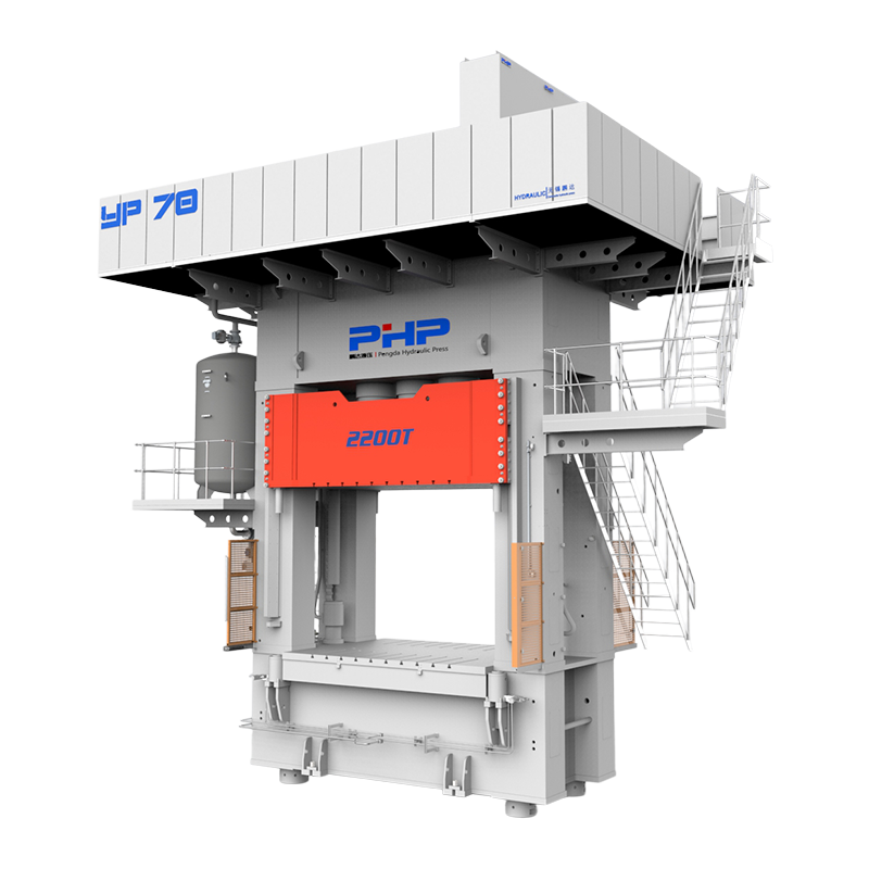
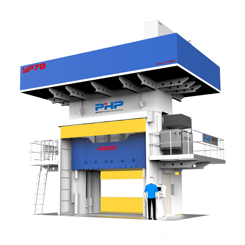
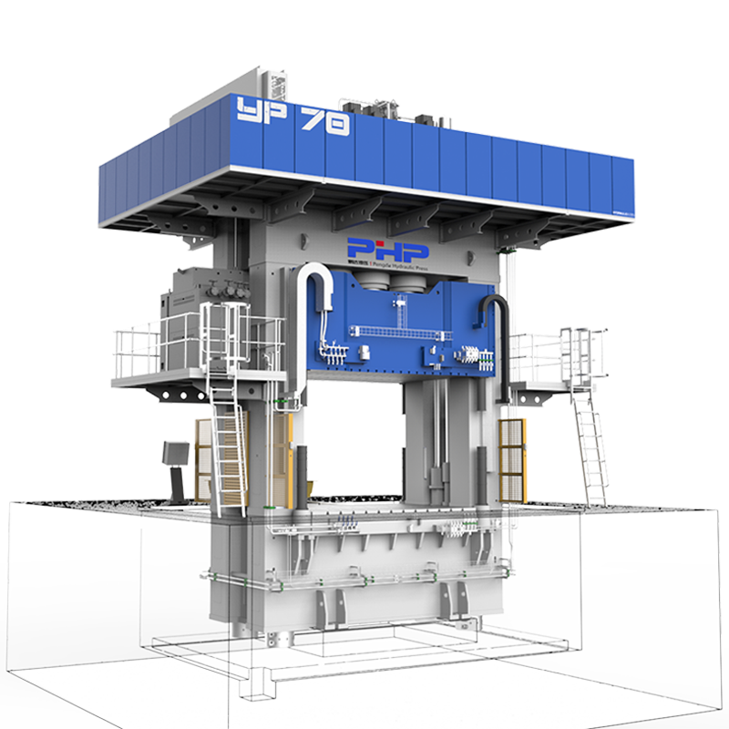
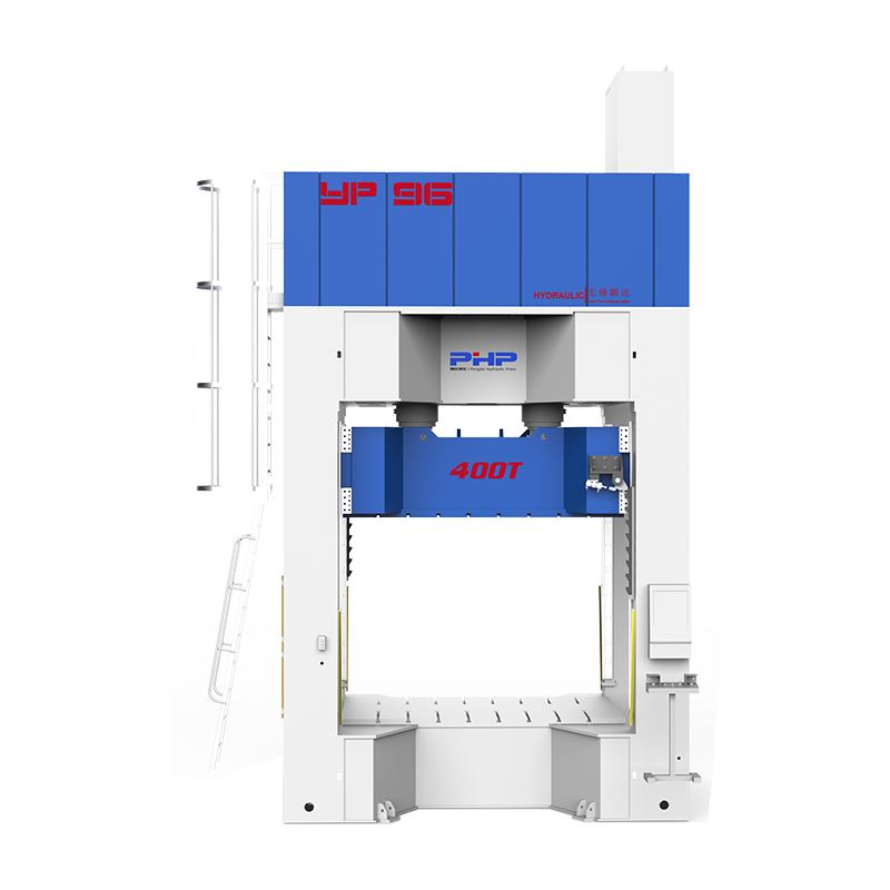
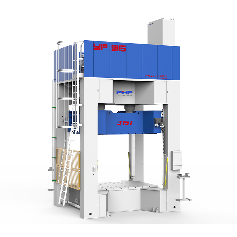
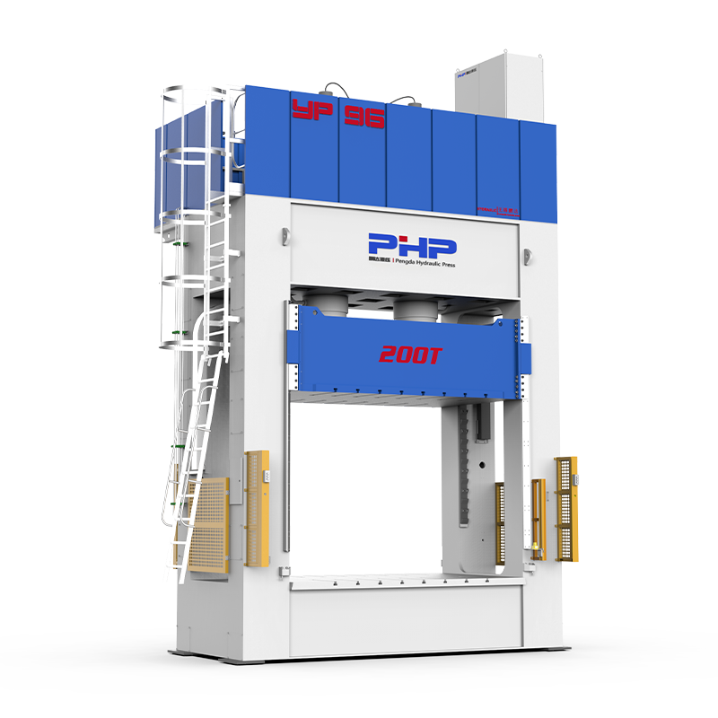


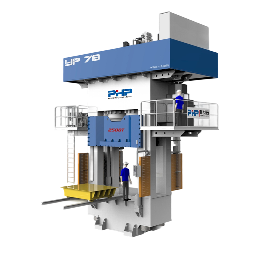
Sheet Molding Compound (SMC) compression molding looks simple from the outside: place a prepared charge in a heated mold, close the hydraulic press, apply pressure, cure the material, and remove the finished part. In production, however, stable SMC molding depends on a much narrower process window.
Charge weight and placement influence material flow. Press closing speed affects fiber movement and trapped air. Mold temperature controls viscosity and resin cure. Pressure determines whether ribs, bosses, edges, and large surfaces fill correctly. Mold design then determines whether the molded part maintains consistent thickness, dimensional accuracy, and surface quality.
For manufacturers producing automotive body panels, battery covers, electrical housings, construction components, and other FRP parts, the press, mold, material, and process parameters therefore need to be treated as one system rather than four separate variables.
Content
- 1 SMC Material Handling, Charge Placement, and Compression Molding Sequence
- 2 Hydraulic Press Tonnage, Closure Speed, and Pressure Application Stages
- 3 Mold Heating Methods, Temperature Ramps, and Uniformity Control
- 4 Cure Time, Viscosity, Flow, and Process Window Optimization
- 5 Mold Design Requirements for Thickness Control and Surface Quality
- 6 Building a Stable SMC Molding Process Window
- 7 FAQ
- 7.1 What hydraulic press tonnage is required for SMC compression molding?
- 7.2 What mold temperature range and heating method are best for SMC parts?
- 7.3 How do you calculate SMC cure time and avoid under-curing or exotherm defects?
- 7.4 What is the correct SMC charge pattern and coverage ratio for uniform part thickness?
- 7.5 What mold design features help prevent SMC surface finish issues and thickness variation?
- 7.6 How does mold closing speed and staged pressure affect SMC flow, fiber orientation, and defects?
- 7.7 Does vacuum-assisted SMC compression molding improve surface quality and reduce porosity?
SMC Material Handling, Charge Placement, and Compression Molding Sequence
SMC processing begins before the material reaches the press.
Commercial SMC is normally supplied as a matured sheet between carrier films. Storage temperature, maturation condition, resin formulation, and supplier instructions determine how the material should be handled. If refrigerated material is used, it should normally be allowed to reach the specified processing condition before molding. Processing cold material directly can change viscosity and flow behavior and may create condensation-related problems.
The required charge weight can be estimated from:
Charge weight = finished molded volume × target material density + process allowance
In production, the calculation should be verified through trial molding because flash, inserts, local ribs, and material distribution affect the actual charge requirement.
Charge coverage is equally important. Research on SMC compression molding shows that initial sheet coverage may vary substantially depending on geometry and the required material flow distance. Experimental studies have evaluated initial charge coverage well below full cavity coverage, while modern research notes that SMC processes can use approximately 20% to 100% of final part area depending on the application.
A smaller charge footprint requires the material to travel farther during closure. That can help fill complex geometry, but excessive flow can increase fiber reorientation, resin/fiber separation, weld-line sensitivity, and local property variation. Research confirms that compression flow can significantly alter local fiber architecture.
A typical molding sequence is:
- Bring the SMC to the specified processing condition.
- Remove carrier films and cut the required charge pattern.
- Weigh and stack the charge.
- Position it according to the validated loading map.
- Close the press rapidly through the non-contact stroke.
- Reduce closing speed as the material begins to compress and flow.
- Build molding pressure according to the programmed profile.
- Hold pressure while the thermoset resin cures.
- Open the mold after sufficient cure.
- Eject the component and inspect flash, fill, dimensions, and surface condition.
Charge geometry should therefore be considered a process parameter—not simply a convenient way to fit material into the mold.
Hydraulic Press Tonnage, Closure Speed, and Pressure Application Stages
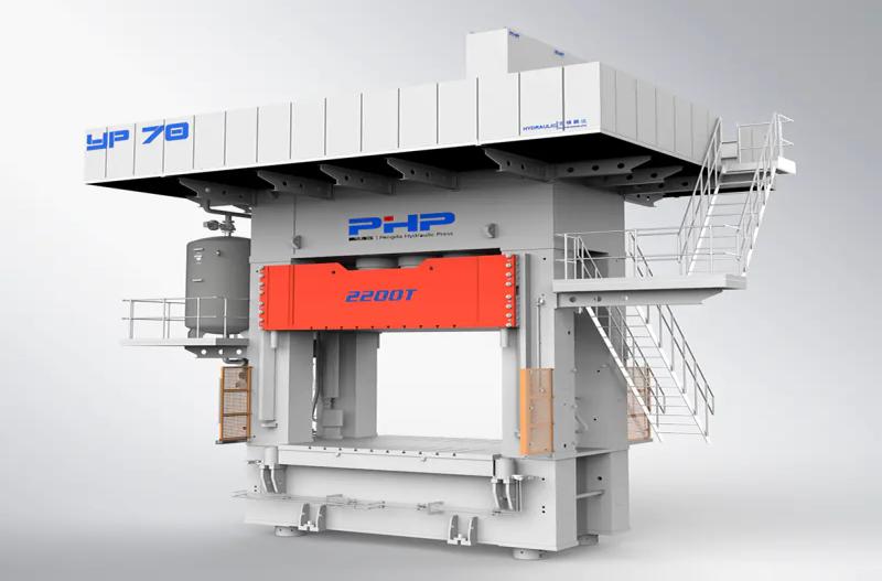
One of the most common SMC press-selection mistakes is choosing tonnage from part weight alone.
Required press force is primarily related to the projected molding area and required cavity pressure:
Required force = projected area × molding pressure
For inch-based calculations:
Press tonnage ≈ projected area (in²) × molding pressure (psi) ÷ 2,000
An additional engineering margin is normally included for process variation, mold configuration, flash area, and future production requirements.
General compression-molding references place thermoset molding pressure around 1,000–2,500 psi on molded surface area, while other SMC literature reports molding pressures of roughly 3–20 MPa depending on formulation and processing conditions. These numbers should be treated as starting ranges rather than universal SMC specifications.
For example, a component with a projected area of 2,000 in² molded at 1,500 psi theoretically requires:
2,000 × 1,500 ÷ 2,000 = 1,500 tons
The required machine could be larger after applying the appropriate safety and process margin.
Press speed is just as important as maximum force.
An SMC servo hydraulic press may use a staged movement profile:
Fast approach → controlled material contact → slow molding closure → pressure build-up → pressure hold
The fast approach reduces non-productive cycle time. Once the upper tool contacts the charge, the ram slows so the SMC can flow through ribs, corners, and large surfaces without uncontrolled displacement.
Closing speed influences pressure history, filling behavior, and fiber orientation, which is why it should be programmable rather than treated as a fixed machine speed. Research into SMC processing identifies mold closing speed, mold temperature, and charge conditions as key variables governing material flow.
This is also where servo-controlled hydraulic presses provide practical value. Wuxi PengdaHZ’s composite press platform uses closed-loop control of pressure, speed, and displacement, allowing different movement and pressure stages to be programmed for the molding cycle.
Vacuum-assisted molding can be added where trapped air, porosity, or demanding surface requirements are important. The mold is evacuated during an appropriate stage of closure before full molding pressure is established.
Mold Heating Methods, Temperature Ramps, and Uniformity Control
SMC is a thermosetting material, so the mold must provide enough heat to reduce compound viscosity initially and then initiate and complete the resin crosslinking reaction.
A commonly referenced SMC mold-temperature region is approximately 140–160°C (284–320°F), although the correct setting depends on the resin system, initiator package, part thickness, geometry, and surface requirement. Published SMC processing references similarly report molding temperatures in this general region.
Three heating methods are commonly considered.
| Heating method | Main characteristics | Typical consideration |
|---|---|---|
| Electric cartridge/heater | Simple installation and independent zoning | Requires good heater distribution |
| Thermal oil | Good heat transfer and controllability | Requires heater, pump, piping, and oil circuit |
| Steam | Rapid heat transfer in suitable tooling | Requires steam infrastructure and condensate control |
The nominal setpoint, however, tells only part of the story.
A mold reading 150°C at one sensor may still contain regions operating substantially hotter or colder. Temperature differences across the cavity can change local viscosity and cure rate, resulting in uneven shrinkage, gloss differences, warpage, premature curing, or incomplete filling.
Large SMC molds should therefore be divided into practical heating zones, with thermocouples positioned to represent critical cavity regions rather than only the heater circuit.
Before production starts, the tool should reach not only its target temperature but also thermal equilibrium. Production should not begin simply because one controller reaches its setpoint.
The same principle applies to the upper and lower mold halves. Their temperature difference should be deliberately controlled. Some specialized processes intentionally use different upper and lower temperatures, but uncontrolled imbalance can create differential cure and dimensional distortion.
For thick sections or difficult flow paths, a lower mold temperature combined with a longer curing period may be preferable. Composite processing guidance specifically notes that thick SMC sections generally benefit from lower temperature and longer cure to obtain a more uniform reaction through the section.
Cure Time, Viscosity, Flow, and Process Window Optimization
There is no universal answer such as “SMC requires 90 seconds to cure.”
The required cure time depends on:
- resin and initiator chemistry;
- mold temperature;
- component thickness;
- charge temperature;
- filler and fiber content;
- local thick sections;
- required demolding strength;
- part geometry; and
- the exothermic behavior of the formulation.
Published compression-molding literature reports pressure-hold cycles in the range of roughly 1–4 minutes for some SMC processes, but this should be treated only as a reference range.
The important point is that SMC viscosity does not remain constant during the molding cycle.
After the charge contacts the hot tool, viscosity initially reaches a condition where the material can flow under pressure. The compound spreads through the cavity while fibers rotate and align with the flow. As temperature continues to increase and the cure reaction accelerates, viscosity rises rapidly until flow effectively stops.
The useful processing window therefore exists between:
sufficient softening for mold filling and excessive cure that prevents further flow.
If the mold is too hot or closure is too slow, the resin may begin curing before long flow paths have filled. If temperature is too low, the cavity may fill but curing can take too long or remain incomplete.
Typical symptoms provide useful clues:
| Defect | Possible process causes |
|---|---|
| Under-cure | Low mold temperature, insufficient hold time |
| Incomplete fill | Low pressure, premature cure, poor charge location |
| Blister/bubble | Trapped gas, moisture, insufficient venting |
| Scorch/local over-cure | Excessive local temperature or long exposure |
| Warpage | Uneven mold temperature, cure gradient, fiber orientation |
| Weld line | Charge pattern and opposing flow fronts |
| Resin-rich area | Excessive flow or fiber/resin separation |
Process optimization should therefore change one controlled variable at a time and record actual pressure, position, temperature, and cycle data instead of relying only on operator observation.
Mold Design Requirements for Thickness Control and Surface Quality
Even a highly repeatable hydraulic press cannot compensate for an unsuitable SMC mold.
Tool design directly affects flow, venting, flash formation, dimensional repeatability, and surface appearance.
Shear edges help control the material as the tool reaches the final closing position and contribute to flash control.
Vents should allow displaced air and volatile gases to escape without creating unacceptable resin loss. Poor venting can contribute to trapped gas, incomplete surfaces, burns, and porosity.
Draft angles must allow reliable release without damaging textured or Class-A surfaces.
Ejector placement should distribute removal force sufficiently to prevent local deformation of a still-hot molded part.
Thickness is largely defined by the closed mold geometry. Rib, boss, insert, and transition design should therefore be considered together with SMC flow behavior. Large abrupt changes in section thickness can create local cure, shrinkage, and surface problems.
Toolmakers must also compensate for the expected shrinkage of the selected SMC formulation rather than applying one generic shrinkage factor to every compound.
For high-quality visible components, surface problems such as pinholes, sink marks, waviness, and uneven gloss cannot always be corrected by simply increasing press pressure. Charge layout, local tool temperature, venting, cavity finish, cure behavior, and tool stiffness may all contribute.
In-mold coating (IMC) can also be incorporated when the application requires improved paintability or surface quality. Its injection point, mold opening sequence, pressure, coating quantity, and timing must be designed into the complete molding cycle rather than added as an afterthought.
This is why the SMC mold, hydraulic press, heating system, and material specification should ideally be evaluated together during project development.
Building a Stable SMC Molding Process Window
Successful SMC compression molding is not achieved by maximizing any single parameter.
More pressure does not automatically produce a better part. Higher mold temperature does not automatically increase productivity. Faster closing does not always shorten the real cycle.
The objective is to create a repeatable process window in which:
charge placement controls flow → press speed controls material movement → pressure completes cavity filling → temperature controls viscosity and reaction → cure time develops sufficient part strength → mold design controls final geometry and surface quality.
Before selecting an SMC molding press, manufacturers should therefore provide the equipment supplier with the component’s projected area, dimensions, material system, expected cavity pressure, mold dimensions, target cycle time, heating method, closing-speed requirements, vacuum requirement, and any IMC process requirements.
Wuxi PengdaHZ Intelligent Equipment Co., Ltd. develops servo composite hydraulic presses for SMC and other composite compression-molding processes. For a new SMC project, manufacturers can use a process-parameter checklist, request a press-tonnage and temperature-control evaluation, or provide part and mold information for a preliminary molding-process assessment.
FAQ
What hydraulic press tonnage is required for SMC compression molding?
Calculate the projected molding area and multiply it by the required cavity pressure. For inch units:
Tonnage = projected area (in²) × pressure (psi) ÷ 2,000.
Then add an appropriate engineering margin. The final pressure requirement should come from the SMC material supplier, mold design, and molding trials rather than using one fixed psi value for every part.
What mold temperature range and heating method are best for SMC parts?
Many conventional SMC systems are processed around 140–160°C, but the material manufacturer’s processing specification should determine the initial setpoint. Electric heating and thermal-oil heating are both common solutions. Temperature uniformity across the mold is usually more important than simply choosing the highest heating power.
How do you calculate SMC cure time and avoid under-curing or exotherm defects?
Start with the SMC supplier’s recommended temperature and cure data, then validate it according to actual part thickness, mold temperature, resin system, and demolding requirement. Thick sections may require lower temperatures and longer cure periods to limit excessive internal exotherm.
What is the correct SMC charge pattern and coverage ratio for uniform part thickness?
There is no universal percentage. The charge should contain the correct mass and be positioned so the required flow distances are achievable without excessive fiber movement, weld lines, or resin/fiber separation. Complex parts should be optimized through flow simulation and molding trials.
What mold design features help prevent SMC surface finish issues and thickness variation?
Important features include accurate closed-tool dimensions, suitable shear edges, effective venting, controlled draft, balanced ejection, uniform heating zones, appropriate rib transitions, shrinkage compensation, and sufficient mold rigidity.
How does mold closing speed and staged pressure affect SMC flow, fiber orientation, and defects?
Fast approach reduces idle cycle time, while controlled slow closure after material contact determines how rapidly the charge spreads. Excessively aggressive flow can alter fiber orientation and material distribution. Programmable speed and pressure stages allow the process to be adjusted according to cavity filling rather than applying full force immediately.
Does vacuum-assisted SMC compression molding improve surface quality and reduce porosity?
It can. Evacuating trapped air before final compression can reduce air-related voids and improve molding consistency, particularly for large or appearance-sensitive components. However, vacuum cannot compensate for poor charge placement, inadequate mold venting, incorrect material condition, or an unsuitable pressure-temperature window.