English
 中文简体
中文简体 Español
 Português
 Deutsch
 русский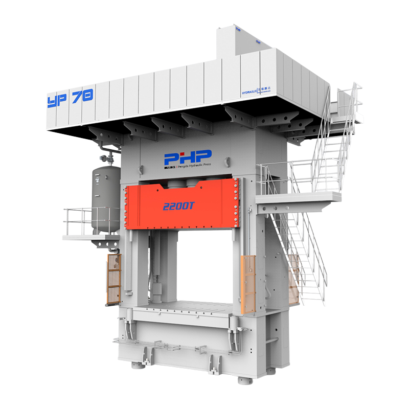


SMC Compression Molding Technology
Achieving a smooth, consistent surface is one of the most demanding requirements in Sheet Molding Compound (SMC) compression molding. This is especially important for automotive exterior panels, electrical enclosures, visible equipment covers, battery housings and other parts where appearance matters as much as mechanical performance.
Surface defects may include flow marks, fiber read-through, waviness, pinholes, blisters, sink marks, resin-rich areas or uneven gloss. Some defects are visible immediately after demolding, while others become obvious only after sanding, coating or paint baking.
Content
- 1 1. What Defines Good SMC Surface Quality?
- 2 2. Surface Quality Starts with the SMC Material
- 3 3. Optimize Charge Pattern and Reduce Unnecessary Material Flow
- 4 4. Control Mold Temperature and Temperature Uniformity
- 5 5. Optimize Closing Speed, Pressure Development and Venting
- 6 6. Mold Surface and Tool Design Directly Affect Appearance
- 7 7. Platen Parallelism Also Influences Surface Consistency
- 8 8. Prevent Porosity Before Painting
- 9 9. Practical Troubleshooting Matrix for SMC Surface Defects
- 10 10. Build a Surface Quality Control Plan
- 11 Improve Surface Quality by Controlling the Complete SMC Molding System
- 12 SMC Compression Molding Solutions from Wuxi PengdaHZ
- 13 Frequently Asked Questions
- 13.1 What causes fiber read-through in SMC parts?
- 13.2 What causes flow marks in SMC compression molding?
- 13.3 How can pinholes and porosity be reduced in SMC parts?
- 13.4 How does mold temperature affect SMC surface quality?
- 13.5 Does higher molding pressure always improve SMC surface finish?
- 13.6 How does charge coverage affect SMC surface quality?
- 13.7 What causes sink marks behind ribs in SMC parts?
- 13.8 How does platen parallelism affect SMC surface quality?
- 13.9 What is Class A surface quality in SMC?
- 13.10 How can SMC surface defects be reduced before painting?
1. What Defines Good SMC Surface Quality?
Surface quality requirements depend heavily on the final application.
For an industrial enclosure or structural component, an acceptable molded surface may primarily require:
- no exposed fibers;
- no visible blisters;
- limited flow marks;
- acceptable dimensional accuracy;
- consistent texture.
Automotive exterior parts have considerably more demanding appearance requirements.
Class A Surface
Class A is commonly used to describe highly visible painted surfaces that require low waviness, limited fiber print-through, minimal porosity and consistent paint appearance.
| Surface Issue | Typical Appearance | Main Concern |
| Fiber Read-Through | Fiber pattern visible through the surface | Cosmetic appearance |
| Flow Marks | Directional or wavy lines | Surface uniformity |
| Pinholes | Small surface pores | Painting defects |
| Blisters | Raised bubbles or localized swelling | Appearance and coating quality |
| Sink Marks | Local depressions | Waviness and reflected appearance |
| Resin-Rich Areas | Glossy or irregular zones | Uneven appearance |
| Waviness | Long-range surface distortion | Class A appearance |
2. Surface Quality Starts with the SMC Material
Process optimization cannot fully compensate for an unsuitable material formulation.
SMC typically combines thermosetting resin, chopped reinforcement, mineral fillers, initiators and other additives. Changes in resin shrinkage, viscosity, fiber content and cure behavior can all affect the final molded surface.
Resin System
Resin chemistry affects viscosity, cure response, shrinkage and how well the material reproduces the mold surface.
Low-Profile Additives
Low-profile additives help control cure shrinkage and can reduce fiber print-through, sink marks and surface waviness.
Fiber Content
Higher reinforcement levels may improve structural performance but can increase sensitivity to fiber read-through and flow-related surface variation.
Mineral Fillers
Fillers influence rheology, dimensional stability, shrinkage and the overall surface response during curing.
Important:
Better surface quality cannot always be achieved by simply adding more resin. Mechanical performance, flow behavior, shrinkage control and appearance must be balanced together.
3. Optimize Charge Pattern and Reduce Unnecessary Material Flow
Charge design begins affecting surface quality before the press starts moving.
The size, position, number of layers and orientation of the SMC charge determine how far the material must travel to fill the cavity.
Low Charge Coverage→Longer Flow Distance→More Fiber Reorientation→Higher Risk of Surface Variation
Excessive material flow can increase:
- fiber reorientation;
- resin/fiber redistribution;
- flow marks;
- local porosity;
- surface waviness;
- air entrapment.
Design the Charge Around the Part
Charge placement should consider:
- ribs and bosses;
- thick and thin sections;
- distant corners;
- last-fill locations;
- visible cosmetic surfaces;
- expected venting points.
Surface quality begins before the press starts moving. The charge pattern determines how the SMC will flow through the mold.
4. Control Mold Temperature and Temperature Uniformity
Mold temperature strongly affects SMC viscosity, material flow, cure rate, shrinkage and demolding behavior.
If the Mold Is Too Cold
- slower curing;
- longer cycle time;
- unstable surface replication;
- poor demolding behavior;
- possible under-cure.
If the Mold Is Too Hot
- premature gelation;
- incomplete material flow;
- visible flow boundaries;
- short shots;
- higher residual stress.
Temperature Uniformity Matters as Much as the Setpoint
A controller showing 145°C does not prove that the complete tool is at 145°C.
Temperature should be checked around:
- the center of the mold;
- edges and corners;
- deep sections;
- thick tooling areas;
- heater-adjacent zones;
- recurring defect locations.
Temperature Difference → Different Cure Rate → Different Shrinkage → Waviness / Sink / Warpage
5. Optimize Closing Speed, Pressure Development and Venting
The hydraulic press plays an important role because SMC must flow through the mold before the material reaches sufficient cure.
A stable molding cycle should generally separate the motion into several stages.
01
Fast Approach
The platen travels quickly before contacting the charge to reduce non-productive movement.
02
Controlled Compression
Closing speed is reduced when material flow begins so SMC can fill the cavity more predictably.
03
Pressure Build-Up
Pressure develops after sufficient flow, compacting the material without prematurely restricting filling.
04
Pressure Hold
Stable pressure is maintained through the required cure stage for consistent compaction and dimensions.
What Happens If Closing Speed Is Wrong?
| Condition | Possible Surface Effect |
| Closing Too Fast | Trapped air, unstable flow, excessive fiber movement and flash |
| Closing Too Slow | Premature gelation, flow boundaries and incomplete filling |
| Pressure Too Early | Restricted flow, fiber displacement and excessive flash |
| Pressure Too Late | Insufficient compaction and retained porosity |
Do Not Ignore Venting
Important venting locations often include:
- last-fill regions;
- corners;
- ribs;
- deep pockets;
- areas where two flow fronts meet.
“Improve venting” is not a complete corrective action.
Engineers should determine where the cavity actually fills last and where air or gas is becoming trapped.
6. Mold Surface and Tool Design Directly Affect Appearance
SMC can reproduce the condition of the mold surface closely. Scratches, deposits, corrosion or damaged coatings may therefore appear directly on the finished component.
Routine tooling inspection should include:
- mold surface condition;
- parting-line wear;
- vent cleanliness;
- release-agent buildup;
- guide pins and bushings;
- local damage;
- insert condition.
Use Release Agent Carefully
Too little release agent can cause sticking and surface damage during demolding. Too much can leave residue, create visual variation or interfere with painting and coating.
Pay Attention to Ribs and Bosses
Thick ribs or bosses positioned behind a cosmetic surface can create localized shrinkage and sink marks. Geometry, material distribution, cure shrinkage and temperature should all be reviewed together.
7. Platen Parallelism Also Influences Surface Consistency
Even a high-quality mold cannot deliver a completely uniform part if it closes unevenly under production load.
Poor platen parallelism or excessive structural deflection may create differences in:
- local mold gap;
- compaction;
- pressure distribution;
- material flow;
- part thickness.
Poor Parallelism→Uneven Mold Gap→Uneven Local Pressure→Surface / Thickness Variation
For large automotive panels, battery covers or wide electrical housings, this effect becomes increasingly important because the tooling occupies a larger proportion of the press working area.
8. Prevent Porosity Before Painting
Porosity deserves special attention for painted SMC parts.
A freshly molded component may appear acceptable while still containing small pores below or close to the surface. These can become much more visible after coating and paint baking.
Before Painting, Check
- surface porosity;
- microvoids;
- moisture;
- contamination;
- release-agent residue;
- blister risk.
9. Practical Troubleshooting Matrix for SMC Surface Defects
Different surface defects can have several possible root causes. A structured troubleshooting matrix helps avoid random parameter changes.
| Defect | Possible Material Cause | Mold Cause | Press / Process Cause | First Check |
| Fiber Read-Through | Shrinkage, fiber distribution | Surface replication | Excessive material flow | Material formulation and charge coverage |
| Flow Marks | Rheology variation | Flow restriction | Closing velocity | Charge layout and speed profile |
| Pinholes | Air or volatile content | Poor venting | Insufficient compaction | Vent locations |
| Blisters | Moisture, volatiles, under-cure | Trapped gas | Premature opening | Material condition and cure |
| Sink Marks | Cure or thermal shrinkage | Rib or boss geometry | Temperature variation | Geometry and temperature |
| Flash | Excess charge | Worn parting line | Excess pressure or poor parallelism | Charge weight and mold condition |
| Resin-Rich Areas | Resin/fiber separation | Local geometry | Excessive flow | Charge pattern |
| Waviness | Shrinkage and fiber effects | Tool geometry | Uneven temperature or compaction | Material, thermal map and pressure |
10. Build a Surface Quality Control Plan
The most effective way to improve surface quality is to turn successful process conditions into a repeatable production window.
| Parameter | Why Monitor It? |
| Material Lot | Detect formulation variation |
| Charge Weight | Maintain filling consistency |
| Charge Coverage | Control flow distance |
| Mold Temperature | Control material flow and cure |
| Temperature Uniformity | Reduce local cure and shrinkage differences |
| Closing Velocity | Control flow and air evacuation |
| Pressure Build-Up | Control timing of compaction |
| Holding Pressure | Improve cycle repeatability |
| Cure Time | Maintain surface and dimensional stability |
| Mold Surface Condition | Maintain consistent surface replication |
| Porosity / Flash Rate | Track surface-quality performance |
Build a Validated Process Window
Instead of relying on one fixed number, establish acceptable ranges for:
Temperature Range
Closing Velocity Range
Pressure Range
Cure-Time Range
Where press controls allow it, recording position + velocity + pressure + time for each cycle can help connect surface defects with actual machine behavior.
Improve Surface Quality by Controlling the Complete SMC Molding System
High-quality SMC surfaces are not created by one pressure setting, one mold temperature or one special material.
Material+Charge Pattern+Mold+Temperature+Venting+Press Motion+Pressure+Cure
For appearance-critical parts, the process should also consider what happens after molding. Porosity, shrinkage and surface instability can become much more obvious after sanding, coating or paint baking.
The most productive troubleshooting approach is to identify which measurable condition changed before the defect appeared, then adjust one variable at a time and validate the result.
SMC Compression Molding Solutions from Wuxi PengdaHZ
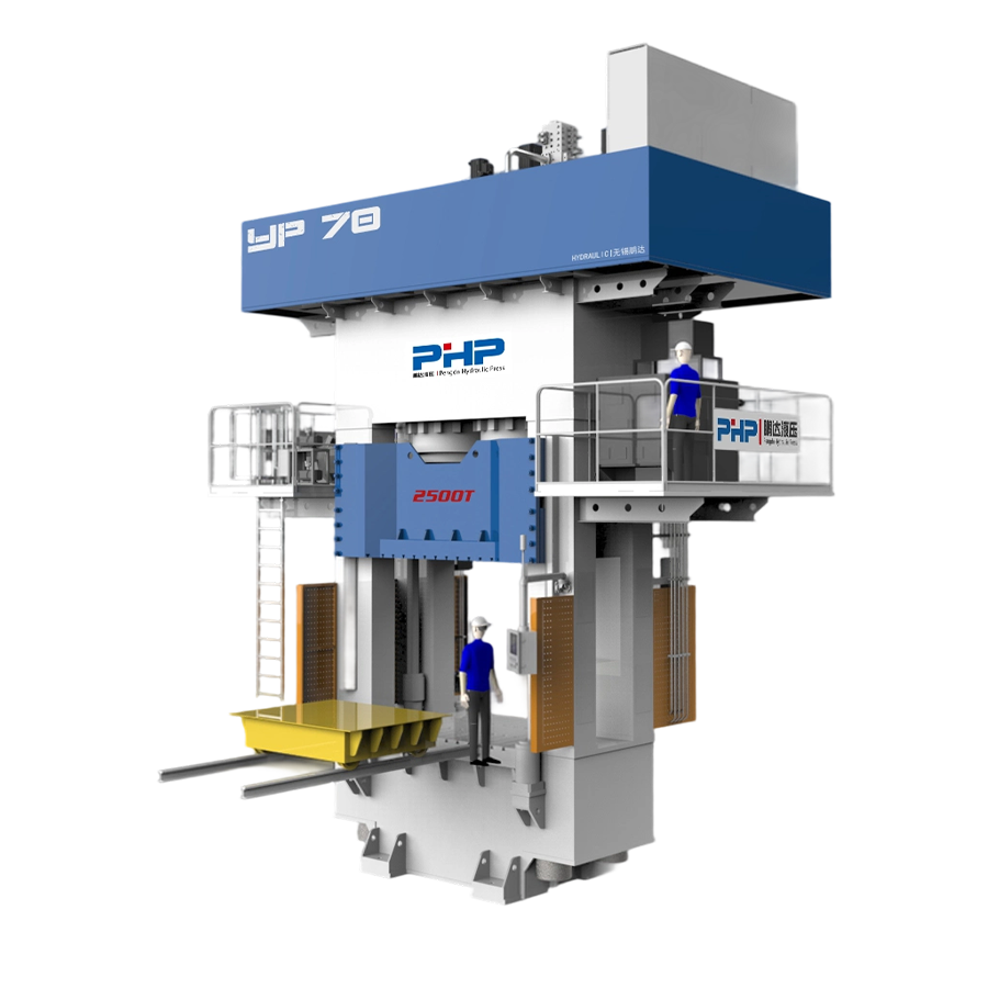
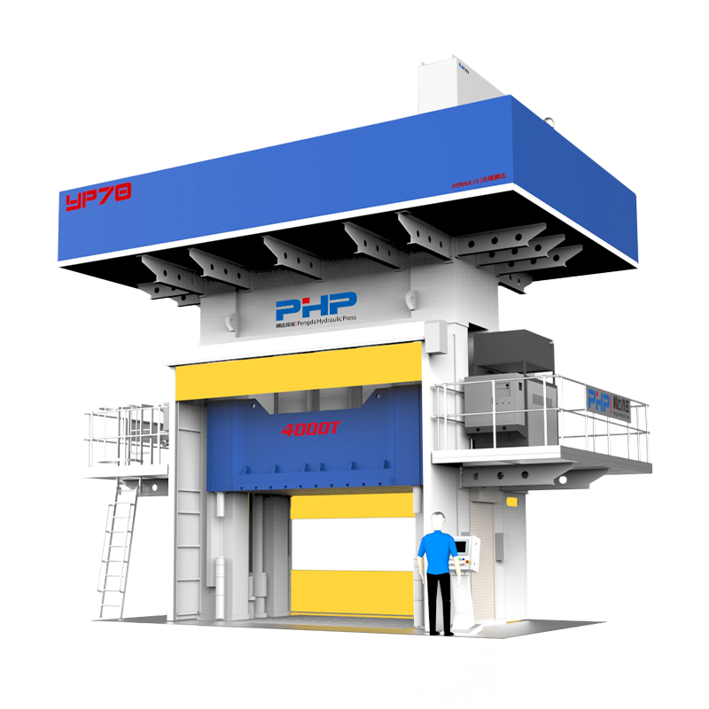
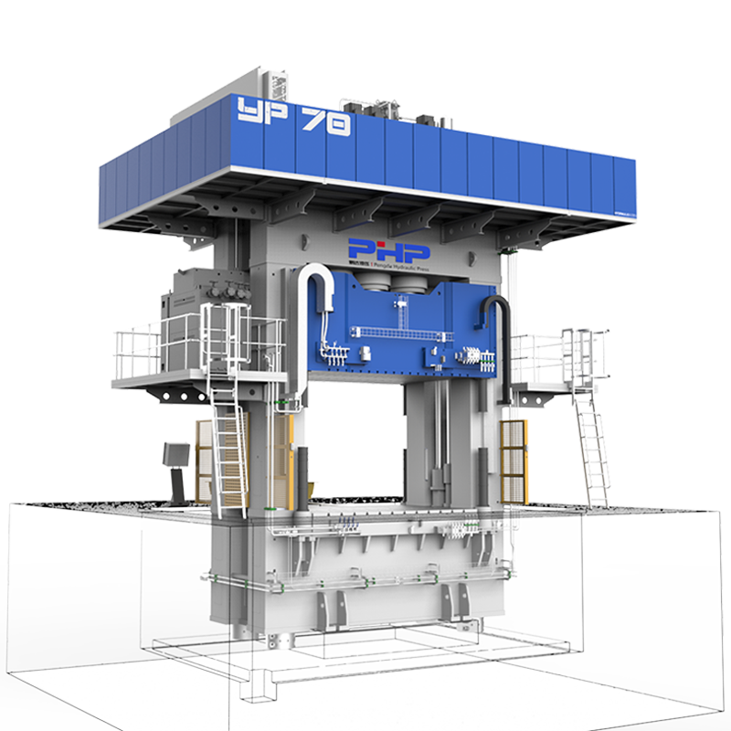
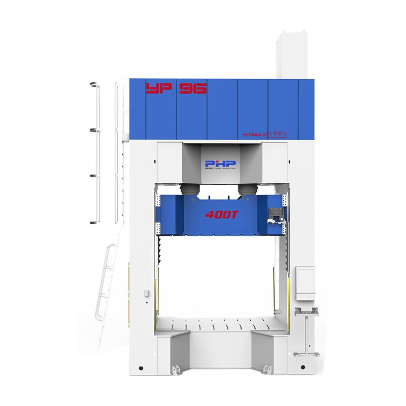
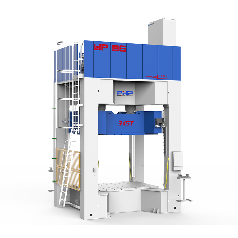
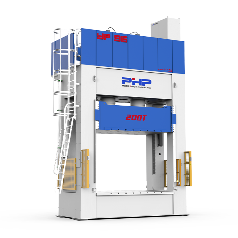
Wuxi PengdaHZ Intelligent Equipment Co., Ltd. develops hydraulic press systems for SMC, BMC and composite compression molding applications.
For manufacturers producing appearance-sensitive SMC components, press selection should consider more than maximum tonnage.
Important factors include multi-stage closing-speed control, pressure build-up, holding-pressure stability, ram position repeatability, platen stiffness and parallelism, cycle-data monitoring and automation interfaces.
When evaluating an SMC press, useful information includes the product drawing, SMC material, mold dimensions, required molding pressure, required surface quality, part thickness, target cycle time and production capacity.
Visit wuxipd.com for more information about customized SMC compression molding presses and composite molding equipment.
Frequently Asked Questions
What causes fiber read-through in SMC parts?
Fiber read-through can be influenced by resin shrinkage, fiber distribution, material flow, surface-layer structure and the formulation used to control shrinkage.
What causes flow marks in SMC compression molding?
Flow marks may result from charge placement, material rheology, excessive flow distance, mold geometry, temperature variation or an unsuitable closing-speed profile.
How can pinholes and porosity be reduced in SMC parts?
Check material condition, charge stacking, venting, flow distance, mold temperature, pressure development and compaction. Porosity should be controlled during molding instead of relying on painting to hide it.
How does mold temperature affect SMC surface quality?
Mold temperature affects viscosity, flow time, cure rate, shrinkage and demolding. Temperature uniformity across the entire tool is also important.
Does higher molding pressure always improve SMC surface finish?
No. Insufficient pressure can cause poor compaction, while excessive or prematurely applied pressure can increase flash and disturb material flow.
How does charge coverage affect SMC surface quality?
Charge coverage determines how far the material must flow. Longer flow paths can increase fiber reorientation, air movement and resin redistribution.
What causes sink marks behind ribs in SMC parts?
Sink marks may result from cure shrinkage, thermal shrinkage, material redistribution, local geometry and temperature differences around the rib or boss.
How does platen parallelism affect SMC surface quality?
Uneven platen closure can change mold gap, pressure distribution, compaction and material flow across the part, potentially contributing to flash and local surface variation.
What is Class A surface quality in SMC?
Class A generally refers to very high cosmetic surface quality suitable for visible painted components such as automotive exterior panels. Exact acceptance criteria vary by customer and application.
How can SMC surface defects be reduced before painting?
Start with stable material formulation, controlled charge placement, uniform mold temperature, effective venting, repeatable press motion and appropriate cure. Surface porosity, contamination and release-agent residue should be controlled before coating.