English
 中文简体
中文简体 Español
 Português
 Deutsch
 русский
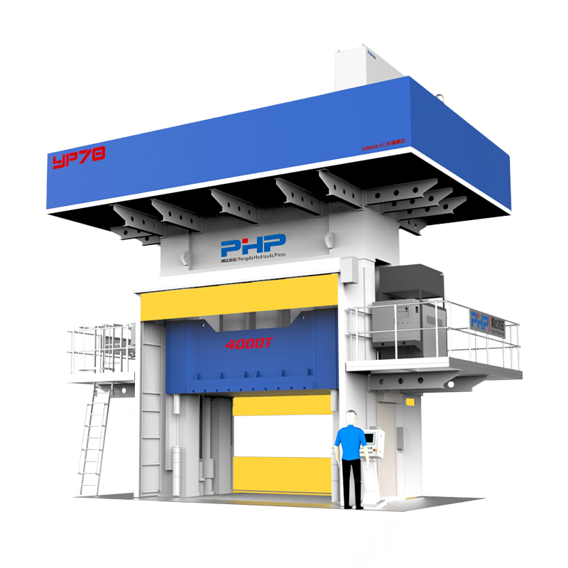
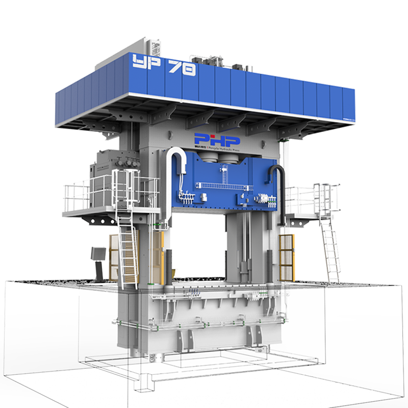
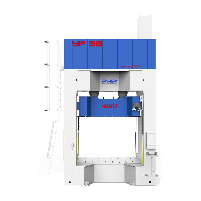
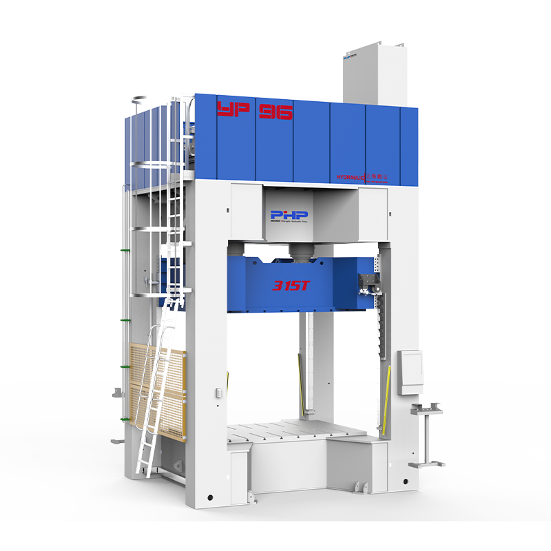
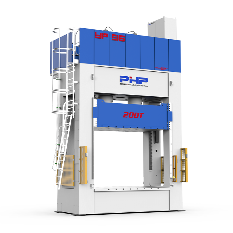

Selecting the correct press tonnage is one of the most important decisions in an SMC compression molding project.
A press that is too small may cause incomplete filling, poor consolidation, or unstable part thickness. An unnecessarily oversized press, however, can increase equipment investment without solving problems caused by poor charge placement, mold design, or process settings.
For preliminary sizing, the basic calculation is straightforward. The challenge is determining the correct projected area, selecting a realistic SMC molding pressure, and converting the calculated force into a practical hydraulic press size.
Content
- 1 1. SMC Clamping Force Formula: From Pressure to Press Tonnage
- 2 2. How to Calculate Projected Area for an SMC Part
- 3 3. Converting Calculated Force into SMC Press Tonnage
- 4 4. Three SMC Clamping Force Calculation Examples
- 5 5. Why Actual SMC Press Force Can Differ from the Calculation
- 6 6. Troubleshooting SMC Problems Related to Press Force
- 7 Quick Unit Conversion Reference
- 8 Need Help Checking the Required Tonnage for Your SMC Mold?
- 9 FAQ
- 9.1 What is the standard formula for calculating SMC clamping force?
- 9.2 What molding pressure should I use when calculating SMC press tonnage?
- 9.3 Should holes and ribs be included in projected area?
- 9.4 How do I calculate force for a multi-cavity SMC mold?
- 9.5 How much additional press capacity should I allow?
- 9.6 Does SMC cure shrinkage require clamping force to change during the cycle?
- 9.7 Why can an SMC part still have defects when press tonnage is sufficient?
1. SMC Clamping Force Formula: From Pressure to Press Tonnage
In SMC compression molding, the term clamping force is often used when discussing machine tonnage. Technically, the hydraulic press generates the molding force required to compress, flow, consolidate, and cure the SMC charge inside the mold.
Metric Calculation
When projected area is expressed in mm²:
When area is measured in cm²:
To convert kN to metric ton-force:
Imperial Calculation
For example, if the projected area is 2,000 in² and the molding pressure is 1,000 psi:
What Molding Pressure Should Be Used for SMC?
There is no universal SMC molding pressure that works for every component. Material formulation, glass-fiber content, charge coverage, flow length, mold temperature, closing speed, ribs, deep-draw geometry, and surface requirements can all affect the actual pressure requirement.
| SMC Part Condition | Example Preliminary Pressure Range |
| Simple, shallow part with favorable charge coverage | 3–7 MPa / 435–1,015 psi |
| General industrial SMC component | 5–10 MPa / 725–1,450 psi |
| Long flow path, ribs, or lower charge coverage | 8–15 MPa / 1,160–2,175 psi |
| Complex structural component or difficult filling | 10–20+ MPa / 1,450–2,900+ psi |
These ranges should be used only as preliminary engineering references. Final molding pressure should be confirmed according to the actual SMC
formulation, component geometry, mold design, and mold-trial results.
Add an Engineering Capacity Margin
The calculated force represents a theoretical molding requirement. It is generally undesirable to operate a production press continuously at its absolute rated capacity.
A preliminary engineering margin of approximately 15–30% may be evaluated according to:
- SMC material batch variation
- Charge positioning variation
- Mold complexity
- Flash sensitivity
- Uneven cavity loading
- Future process optimization
- Pressure required under difficult filling conditions